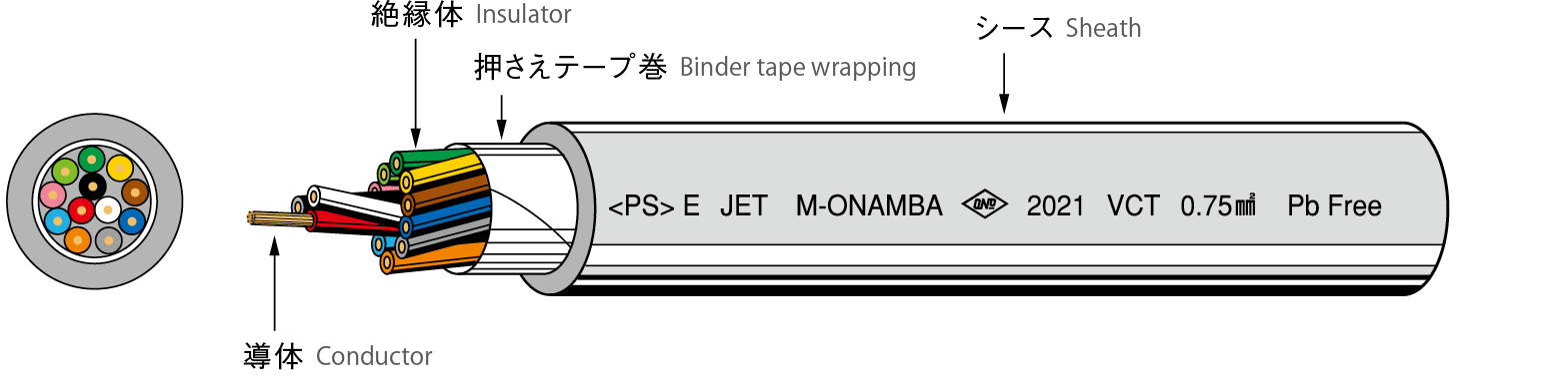
製品名
-
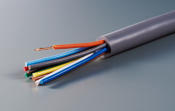
VCT多心/HVCT多心 多心ビニルキャブタイヤケーブル
- 英語名 : Multi-core PVC cabtire cables
-

 製品記号について
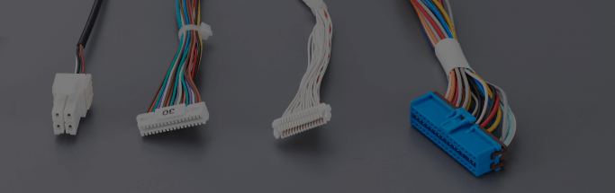
機器内用
製品名


灰
Gray
ケーブルベア・ロボットアーム等の摺動性及び連続屈曲性を要求される環境下での使用はしないでください。
Do not use these products in cable carriers, robot arms, and other environments where sliding performance and continuous bending performance are required.
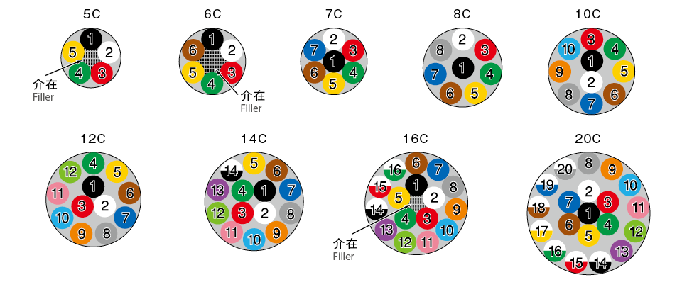
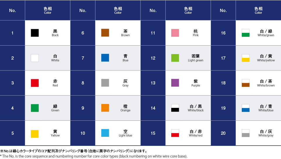
| 線心数 No. of cores |
導体(AC) Conductor (AC) |
絶縁体 Insulator |
撚合 外径 Stranded outer diameter mm |
シース 厚 さ Sheath thickness mm |
仕上 外径 Finished outer diameter mm |
許容電流 (参考値) Maximum permissible current (reference value) A |
概算 重量 Approximate weight kg/km |
|||
|---|---|---|---|---|---|---|---|---|---|---|
| 公 称 断面積 Nominal cross-section area mm² |
構成 素線数/素線径 Configuration No. of wires/ Single wire diameter 本/mm Wires/mm |
外径 Outer diameter mm |
厚さ Thickness mm |
外径 Outer diameter mm |
||||||
| 5C | 0.75 | 30/0.18 | 1.1 | 0.8 | 2.7 | 7.3 | 1.8 | 11.0 | 9 | 155 |
| 1.25 | 50/0.18 | 1.5 | 0.8 | 3.1 | 8.4 | 1.9 | 12.3 | 13 | 195 | |
| 2 | 37/0.26 | 1.8 | 0.8 | 3.4 | 9.2 | 1.9 | 13.1 | 17 | 235 | |
| 3.5 | 45/0.32 | 2.5 | 0.8 | 4.1 | 11.1 | 2.0 | 15.4 | 25 | 360 | |
| 6〜7C | 0.75 | 30/0.18 | 1.1 | 0.8 | 2.7 | 8.1 | 1.8 | 11.8 | 8(8) | 170(180) |
| 1.25 | 50/0.18 | 1.5 | 0.8 | 3.1 | 9.3 | 1.9 | 13.2 | 11(10) | 230(250) | |
| 2 | 37/0.26 | 1.8 | 0.8 | 3.4 | 10.2 | 2.0 | 14.5 | 14(14) | 290(310) | |
| 3.5 | 45/0.32 | 2.5 | 0.8 | 4.1 | 12.3 | 2.1 | 16.8 | 21(20) | 430(470) | |
| 8C | 0.75 | 30/0.18 | 1.1 | 0.8 | 2.7 | 8.9 | 1.9 | 12.8 | 7 | 200 |
| 1.25 | 50/0.18 | 1.5 | 0.8 | 3.1 | 10.2 | 2.0 | 14.5 | 10 | 275 | |
| 2 | 37/0.26 | 1.8 | 0.8 | 3.4 | 11.2 | 2.1 | 15.7 | 13 | 350 | |
| 3.5 | 45/0.32 | 2.5 | 0.8 | 4.1 | 13.6 | 2.2 | 18.3 | 19 | 535 | |
| 10C | 0.75 | 30/0.18 | 1.1 | 0.8 | 2.7 | 10.6 | 2.0 | 15.1 | 7 | 260 |
| 1.25 | 50/0.18 | 1.5 | 0.8 | 3.1 | 12.4 | 2.1 | 16.9 | 10 | 350 | |
| 2 | 37/0.26 | 1.8 | 0.8 | 3.4 | 13.6 | 2.2 | 18.3 | 12 | 455 | |
| 3.5 | 45/0.32 | 2.5 | 0.8 | 4.1 | 16.4 | 2.3 | 21.3 | 18 | 655 | |
| 12C | 0.75 | 30/0.18 | 1.1 | 0.8 | 2.7 | 11.2 | 2.1 | 15.7 | 7 | 300 |
| 1.25 | 50/0.18 | 1.5 | 0.8 | 3.1 | 12.9 | 2.2 | 17.6 | 9 | 400 | |
| 2 | 37/0.26 | 1.8 | 0.8 | 3.4 | 14.1 | 2.2 | 18.8 | 12 | 505 | |
| 14C | 0.75 | 30/0.18 | 1.1 | 0.8 | 2.7 | 11.9 | 2.1 | 16.4 | 6 | 335 |
| 2 | 37/0.26 | 1.8 | 0.8 | 3.4 | 15.0 | 2.3 | 19.9 | 11 | 565 | |
| 16C | 0.75 | 30/0.18 | 1.1 | 0.8 | 2.7 | 12.7 | 2.2 | 17.4 | 6 | 375 |
| 1.25 | 50/0.18 | 1.5 | 0.8 | 3.1 | 14.6 | 2.3 | 19.5 | 8 | 505 | |
| 20C | 0.75 | 30/0.18 | 1.1 | 0.8 | 2.7 | 14.0 | 2.2 | 18.7 | 6 | 445 |
| 1.25 | 50/0.18 | 1.5 | 0.8 | 3.1 | 16.1 | 2.4 | 21.2 | 8 | 605 | |
| 2 | 37/0.26 | 1.8 | 0.8 | 3.4 | 17.6 | 2.5 | 22.9 | 10 | 790 | |
弊社や製品情報、導入実績などについて、お気軽にお問い合わせください。
お問い合わせ