ONAMBA

太陽光用

製品名

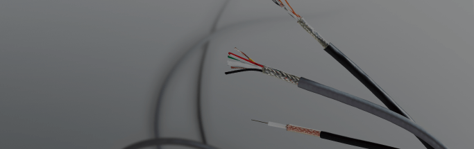
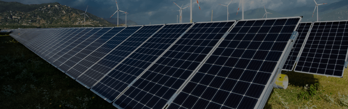
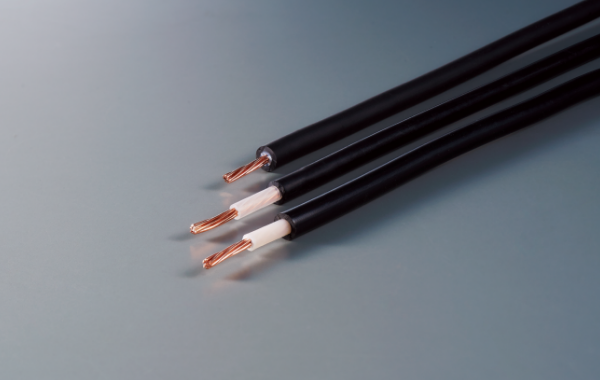
CV、HCV、EM CE/F DC1500V PV-CC 太陽光発電システム用ケーブル(PV ケーブル)

英語名 : Cables for solar power generation systems (PV cables)
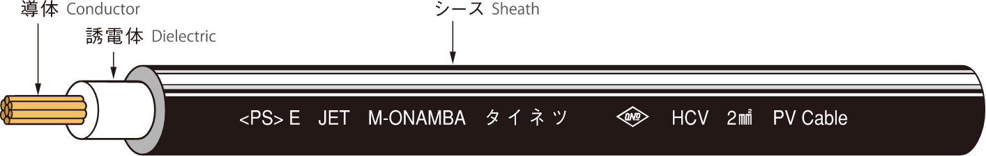
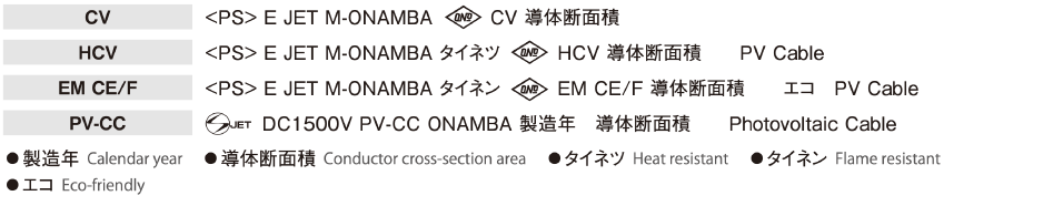
icon-pse.svg icon-pse.svg 製品記号について

用途 Applications

  • DC750V 以下(CV、HCV、EM CE/F)及び DC1,500V 以下(PV-CC)の太陽光発電システムの太陽電池モジュール間、モジュールと接続 箱間及び接続箱とパワーコンディショナー間の直流配線に使用されます。
  • Used as DC cables that connect solar cell modules in solar power generation systems of 750 VDC or less (CV, HCV, EM CE/F) or 1,500 VDC or less (PV-CC), as well as connecting the modules to the connection box and the connection box to the power conditioner.

特長 Features

  • 焼却処理をしても、ダイオキシンやハロゲンガスなどの有害ガスは発生しません。(EM CE/F、PV-CC)
  • 燃焼時に発煙量が少なく、腐食性ガスは発生しません。(EM CE/F、PV-CC)
  • 鉛などの重金属を含んでいないため、埋立処理をしても溶出の恐れがありません。(全品種)
  • PV-CC は太陽光発電用途に特化したケーブルで、遮蔽無しの構造で高圧領域の DC1,500V まで使用できます。
  • These products do not produce dioxins, halogen gas, or other toxic gases when they are incinerated for disposal. (EM CE/F, PV-CC)
  • The amount of smoke produced during incineration is small, and no corrosive gases are produced.(EM CE/F, PV-CC)
  • Because they do not contain lead or any other heavy metals, they can be disposed of in landfill without concern about elution. (All product types)
  • PV-CC cables are specialized for solar power generating applications. They have a shield-less structure and can be used in high-voltage ranges up to 1,500 VDC.

構造図 Structural diagram

表面表示 Surface marking

シース標準色 Sheath standard colors

黒、白(CV、HCV)、黒(EM CE/F、PV-CC)
(ライン識別にも対応いたします。)

Black, white (CV, HCV), black (EM CE/F, PV-CC)
(Line identification is also provided.)

使用上の注意 Precautions for use

  • 周囲環境により配線施工後に電線表面が白くなることがありますが、電線表面の現象で特性に影響はありません。
  • EM CE/F、PV-CC のシース材料は強く擦られると表面に白い跡(筋)が残る傾向(白化現象)があります。電線表面の現象で特性に影響はありませんが取り扱いにはご注意願います。
  • Due to the surrounding environment, the cable surfaces may turn white following cable installation work, however this is a cable surface phenomenon and does not affect
    the characteristics.
  • The surface of the EM CE/F and PV-CC sheath material tends to produce white marks (streaks) on the surface (whitening phenomenon) when the cables are strongly rubbed. This is a cable surface phenomenon and does not affect the characteristics, however care should be used when handling the products.

構造表 Structural table

線心数
No. of cores
導体 (AC)
Conductor (AC)
誘電体
厚さ
Dielectric
thickness

mm
シース
厚 さ
Sheath
thickness
mm
仕上
外径
Finished
outer diameter

mm
導体抵抗
Conductor
resistance

(20°C)
Ω/km
耐電圧
Withstand voltage
(水中)
V/1 分間
(in water)
V/minute
絶縁抵抗
Insulation
resistance

(20°C)
Ω/km
参考値
Reference value
公 称
断面積
Nominal
cross-section
area

mm2
構成
素線数/ 素線径
Configuration
No. of wires /
Single wire
diameter

本 /mm
Wires/mm
外径
Outer diameter
mm
許容電流
(40°C)
Maximum
permissible
current
(40°C)

A
概算
重量
Approximate
weight

kg/km
CV、HCV 2 7/0.6 1.8 0.8 1.5 6.4 9.24 AC 1,500/1 2500 33 60
3.5 7/0.8 2.4 0.8 1.5 7.0 5.20 47 80
5.5 7/1.0 3.0 1.0 1.5 8.0 3.33 62 115
EM CE/F 2 7/0.6 1.8 0.8 1.5 6.4 9.24 33 55
3.5 7/0.8 2.4 0.8 1.5 7.0 5.20 47 75
5.5 7/1.0 3.0 1.0 1.5 8.0 3.33 62 105
PV-CC 2 7/0.6 1.8 0.8 1.2 5.8 9.24 AC 6,500/5 1000 33 50
3.5 7/0.8 2.4 0.8 1.2 6.4 5.20 47 70
5.5 7/1.0 3.0 0.8 1.2 7.0 3.33 62 95
  • CV、HCV の 2mm2 は、心線構成違い(19 本 /0.37mm)の製作も可能です。
  • PV-CC は、電気用品安全法対象外のため PSE マークは表示できません。
  • 許容電流は内線規定 1340-2 などの許容電流より抜粋
  • CV and HCV 2 mm² sizes can also be produced with different core configurations (19 wires / 0.37 mm).
  • PV-CC does not bear the PSE mark because it is not subject to the Electrical Appliances and Materials Safety Act.
  • Maximum permissible current references the maximum permissible current of indoor wiring regulation 1340-2 and other sources.

製品情報

製品検索

弊社や製品情報、導入実績などについて、お気軽にお問い合わせください。

お問い合わせ
TOP >